WRITING AND DECODING
For the decoding of the acquired images we have developed a software that implements a whole series of algorithms that allow to solve the problems we initially found with reading. The software has been realized in two versions, one that runs on computers and the other on Android smart-phones.
Finding the matrix
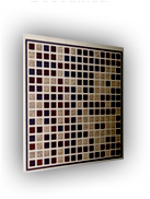
During the first phase of study of the DataMatrix it was immediately clear that a positioning and orientation system was needed in order to make it possible to easily identify the code and to read the bits in the right sequence. In the DataMatrix the positioning of the code is realized through a structure that forms an "L" by black squares on the first column and the last line, while the first raw and the last column are filled with a sequence of alternate white and black squares: in this way it is possible to correctly position the matrix and also to identify the number of rows and columns that compose the code. A side effect, though, is the loss of two entire rows and two entire columns, which cannot contain data. For the CDM we thought of a system that would reduce the loss of space available for data, and we decided to use only the four corners of the matrix, the black squares and a red one, so that the red one is the right inferior corner of the matrix. This implies the loss of only 4 bits of information. The software identifies the four corners, it determines the color of each square, computes the appropriate rotation angle and eventually performs the rotation of the image.In order to correctly "read" the square, we decided that it is appropriate to calculate the average of the color of only part of the surface. This should not be too extended so as to avoid to sample adjacent squares, and at the same time not too small so as to avoid that the possibly poor quality of the acquisition could compromise the measure. The portion of space where the measures are to be performed is located using the gradient between differently colored squares. Knowing the number of rows and columns of the matrix, it is possible to locate the centres of the squares and hence to identify a portion of the square where the coloring is reasonably constant, so that the color acquisition can be safely performed.
Brightness problems
In conditions of poor illumination, the acquisition of the board through devices that do not use their own light source (eg. scanner) as webcams or mobile phones may lead to an incorrect color recognition and thus to incorrect decoding or even impossibility of decoding. The most frequent anomalies are due to the acquisition of green and blue squares as blacks, and the white ones as red.From evaluations carried out on the acquired data, performed on the three color channels, we found that the values were not spaced between 0 and 255, but rather contained in a very small range, of amplitude approximately equal to 150. Consequently, in order to obtain a correct result it was necessary to implement an algorithm for rescaling the values across the width of the channels. If k is the set of values on each channel, dst is the true value of the color channel and src is the value read, for each value of each channel we have that :
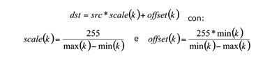
This algorithm ensures that the maximum value possibily read will be 255, and the minimum value 0, while all the other values will be re-scaled whitin this range.
After the introduction of such a procedure, between the phase of acquisition and that of decoding, the system was found to have substantially improved, not only in terms of more correct decoding, but also in terms of an increase of the squares that are read correctly even in blocks with errors. .